This project is about building your own micro controller hardware and software. The micro controller is the Arduino Nano. The development software platform is either PlatformIO or Arduino development studio.
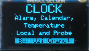
Introduction
After years of programming mainframes, mini-computers, and desktop computers, I decided to try micro controllers. My choice was Arduino nano micro controller. I selected two projects: WayIn Real Time Clock Kit, and Building your own digital thermometer by Barry Lim.
Version 1.2 Daylight saving time. The setup menu allows the user to add one hour in the spring and set the clock back one hour in the fall.
I purchased the Arduino real time clock kit and the parts needed for the building your own thermometer. I wired the breadboards, installed the software, and got the two projects working. However, I found the software overly simplistic. I decided to combine the two projects into one and add new features. In other words, I rewrote the software pushing it against the limit of available memory. The user can select date and time display styles, temperature units and set alarm clock time and duration. The user can set the current date and time. The software will calculate the day of the week. In total, there are 13 setup screens. The permanent values of the setup are saved into non-volatile EEPROM. The Arduino nano is based on the ATmega328 microcomputer. It has only 2K bytes of SRAM memory. One must program carefully to ensure some free stack space is available. The attached software saves the setup screens text in program memory (PROGMEM) to save SRAM.
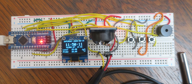
Real Time Clock Project picture
Main Display
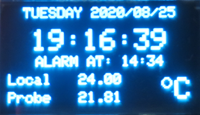 Int Style
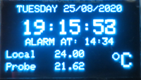 Euro Style
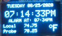 US Style
This project displays the following information in real time.
- Calendar date including day of the week
- Real time clock (hour, minute and second)
- Alarm time (hour and minute)
- Internal temperature of the real time clock module
- External temperature using a temperature probe
- The calendar date can be in one of three formats: yyyy/mm/dd, or dd/mm/yyyy, or mm/dd/yyyy.
- The clock can be in either 24 hours format or 12 hours format.
- The temperature can be in Celsius or in Fahrenheit.
Project’s Parts
To build the project, you need the parts listed below:
- Arduino Nano micro-controller board based on ATmega328P chip
- Display Module OLED SSD1306 128 by 64 0.96”
- Real Time Clock Module DS3231 with battery backup
- Temperature sensor probe DS18B20 with pluggable terminal or 4.7K Ohm resistor
- USB 2.0 cable with Mini-B (5 pin) connector
- Active buzzer 5V
- Three (3) tactile push button switches
- Breadboard
- Breadboard jumper wires
Notes and Suggestions
- The WayIn Real Time Clock Kit contains most of the parts. The temperature sensor must be purchased separately.
- For the temperature sensor probe, you need either pluggable terminal or a 4.7K Ohm resistor.
- Get longer USB Mini-B cable.
- Larger breadboard than the one provided by WayIn.
- The jumper wires are easy to use but the project will look messy. Consider plain wires for breadboard.
Development Software Installation
You need to install an integrated development environment (IDE) on your desktop. It is needed to compile and download the project software to your Arduino Nano. You have two choices, the PlatformIO development studio, or the Arduino development studio. My recommendation is the PlatformIO.
To install PlatformIO, go to PlatformIO Organizion Website and follow the instructions. This software is based on Microsoft Visual Studio Code.
To install Arduino IDE, go to Arduino Micro Controller Website, and follow the instructions.
Hardware Installation
The first step is installing the components on the breadboard. The wiring diagram is given below. The Arduino board is powered by the USB cable. The power source for all other modules is the Arduino board. There are two ground (GND) pins, you can select either one. There are two power sources 5V and 3V3. I selected 5V. To my knowledge, all modules are rated 3 to 5 volts. You can try the 3.3V. The display module and the real time clock modules share 2 wires serial connection. The diagram shows a serial probe without pluggable terminal. If you have pluggable terminal, you do not need the 4.7K Ohm resistor.
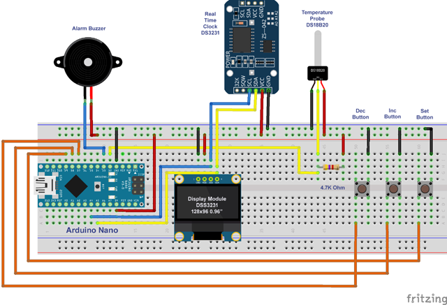
Breadboard wiring diagram
Links to Manuals of Main Components
Software Installation
Any Arduino software project consists of two parts. Main program (main.cpp) and optional libraries. In the case of this project, the main.cpp program is my contribution. The optional libraries support the hardware modules of the project. There are five libraries in total. The source code attached to this article contains both the main program and the libraries. You can download the libraries from their respective source. The attached libraries are as they are at the time this article is written. You can use the links below for future revisions.
Project Installation for PlatformIO IDE
PlatformIO installation creates a projects folder in your private documents area.
C:\Users\<YourUserName>\Documents\PlatformIO\Projects
To install the project source files, follow the steps below:
- Download the RealTimeClock source file. It is a ZIP file. Right click on the downloaded file and extract all files into the projects folder given above.
- You should see a RealTimeClock folder inside the Projects folder.
- Start the PlatformIO (Visual Studio Code) IDE.
- Wait for “Welcome to PlatformIO” page loading to complete.
- If you have another project already open, go to File and Close Folder.
- Click on Open Project.
- Click on Projects.
- You should see RealTimeClock folder.
- Click on RealTimeClock and again click on Open “RealTimeClock”.
- The project will be loaded.
- Click on the PlatformIO icon at the left edge of the screen.
- In Project Tasks, click on Build.
- The project will be compiled. You should see SUCCESS at the end of terminal text.
- Connect your wired project breadboard with USB cable to your desktop computer.
- In Project Tasks, click on Upload.
- The project will be compiled again and uploaded into the Arduino. You should see SUCCESS at the end of terminal text.
- The project LCD screen should display an initialization message for 2 seconds.
- Next, you should see the main screen of the project. The date, time and two lines of temperature.
#include Note: During the software development, I run into a problem. PlatformIO issued an error message lib\Adafruit GFX Library/Adafruit_MonoOLED.h:30:32: fatal error: Adafruit_I2CDevice.h: No such file or directory. The header file, Adafruit_I2CDevice.h, was installed properly. To solve the problem, I added two #include lines in main.cpp.
#include <Adafruit_I2CDevice.h>
#include <Adafruit_SPIDevice.h>
These lines are not required by main.cpp. However, they solve the problem. To be clear, the error message should not have been there, and I do not understand why these two lines solve the problem..
Project Installation for Arduino Studio IDE
- Start the Arduino Studio IDE.
- If there is an active project, go to File and select New. A new project window will be displayed. Close the first window.
- Extract main.cpp from the RealTimeClock zip file. It is in the src folder.
- Open it with Notepad. Go to Edit and Select All. Go to Edit again and select Copy.
- Go to the Arduino Studio. Go to Edit and Select All. Go to Edit again and select Paste.
- Go to File and select Save As. Save the file as
RealTimeClock. - Click on Verify. You will get an error that one of the include files is missing. In other words, you need to add a library.
- Click on Sketch and select Include library.
- Click on Manage Libraries. In the search field, type the name of the missing library. Find the library and press Install. If the library is dependent on another library, load all the dependent libraries.
- You will need to repeat the last 4 steps a few times. When all the libraries are loaded, the verify is successful.
- Connect your wired project breadboard with USB cable to your desktop computer.
- Click on Upload.
- The project will be compiled again and uploaded into the Arduino.
- The project LCD screen should display an initialization message for 2 seconds.
- Next, you should see the main screen of the project. The date, time and two lines of temperature.
User Setup
After project downloading, you need to set the date and time, and to set display preferences.
The project has three push buttons:
- Set button is connected to pin D9.
- Inc button is connected to pin D8.
- Dec button is connected to pin D7.
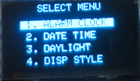
Press the Set button for at least 2 seconds. The system will switch to setup mode. There will be four choices. (1) Alarm Clock, (2) Date Time, (3) Daylight, and (4) Display Style. Use the Inc or Dec buttons to select one of the four options. Press the Set button to accept, and move to the next step,
If at any time during the setup process, all the three buttons are not pressed for 12 seconds, the setup mode is cancelled, and the normal clock screen is displayed.
Alarm Clock Setup. The first choice is Alarm Off and Alarm On. Select and press Set. Alarm Off takes you back to normal clock screen. Alarm On gives you three more screens: Hour, Minute, and alarm duration in seconds. Press Set after each screen.
Date Time Setup. There are five screens to set. Year, month, day-of-the-month, hour, and minute. The day-of-the-week is calculated from the date. If you want your clock to be very accurate, set the minute value to one more than your phone or desktop. Wait for the time on your accurate device to change and press Set immediately.
Daylight Setup. There are three choices: Cancel, Spring +1 Hour, and Fall -1 Hour. This option allows the user to advance the clock by one hour forward in the spring. And to set the clock back by one hour in the fall. The software will ensure that the clock's minutes and seconds are not effected. Further, if the user adds one hour at 11 oclock at night, the hour and date will change accordingly. Similarly, if the user set the clock back right after midnight, the software will set the hour and date appropriately.
Display Style. There are three screens to set your main screen display style.
- The calendar date can be in one of three formats: yyyy/mm/dd or dd/mm/yyyy or mm/dd/yyyy.
- The clock can be in either 24 hours format or 12 hours format.
- The temperature can be in Celsius or Fahrenheit. Press Set after each screen.
Arduino Nano Limited SRAM
The Arduino nano has only 2K bytes of SRAM memory. If you use too many static text strings, or if you use standard library methods such as sprint(), it is likely that there will be no free stack space available. Your software will crash. It will either freeze or reboot the Arduino. I found a small method at this site. It is available at the end of main.cpp source code. It is commented out. If you call getFreeMemory() from any method, it will display the number of bytes available for the stack. In my case, I called it at the end of tempToStr(int temp) method.
History
- 2nd September, 2020: Version 1.0 Original version
- 3rd September, 2020: Version 1.1 change of
#include file Adafruit_MonoOLED.h - 4th September, 2020: Version 1.2 Daylight saving time
This member has not yet provided a Biography. Assume it's interesting and varied, and probably something to do with programming.
 General
  News
News  Suggestion
  Question
  Bug
Bug  Answer
  Joke
Joke  Praise
  Rant
Rant  Admin
Admin 


